



How to Change a Tire for Maximum Performance and Safety
Changing a tire is straightforward. Changing it correctly is a different standard entirely.
Most drivers focus on getting the wheel back on. Few consider whether the torque is right, the hub surface is clean, or the bead is seated evenly. Those details won’t stop you from moving from A to B. They will, however, determine how your tire performs, how long it lasts, and how the wheel assembly holds under braking, cornering, and load.
A tire is a precision-engineered component. Its compound, casing, and tread architecture are built to perform within specific parameters. Those parameters begin at the moment of fitment. Get the installation right, and the tire delivers everything it was designed for. Get it wrong, and the degradation starts immediately, often invisibly.
What You Need Before You Start
Most tire changes go wrong before the first nut is touched. Using the wrong tools, or missing one entirely, removes any chance of fitting the tire to the precision it was engineered for.
The torque wrench is non-negotiable.
Without it, there is no way to apply the correct clamping force to the wheel. A standard wheel brace tells you nothing about how much force you're using. Too little and the wheel settles loose. Too much and you risk stretching the studs or warping the brake rotor. Neither outcome is visible until the damage is done.
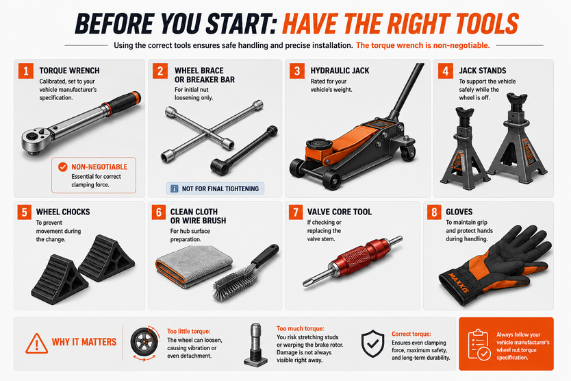
Before starting, have the following ready:
- Torque wrench — calibrated, set to your vehicle manufacturer's specification
- Wheel brace or breaker bar — for initial nut loosening only
- Hydraulic jack — rated for your vehicle's weight
- Jack stands — to support the vehicle safely while the wheel is off
- Wheel chocks — to prevent movement during the change
- Clean cloth or wire brush — for hub surface preparation
- Valve core tool — if checking or replacing the valve stem
- Gloves — to maintain grip and protect hands during handling
Your vehicle's torque specification is in the owner's manual. If you're fitting aftermarket wheels, the specification is in the wheel's certification documentation.
How to Remove the Tire Safely
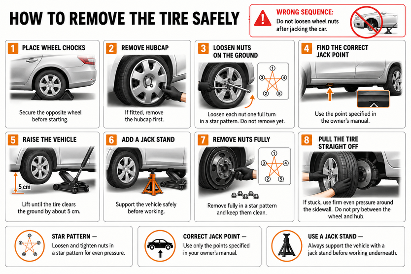
Most drivers loosen the wheel nuts after jacking the car. That's the wrong sequence. With the wheel off the ground, the hub spins freely under force, making it impossible to break the nuts loose cleanly and safely.
Loosening happens first, on the ground, before the jack touches the vehicle.
1. Position the wheel chocks on the opposite wheel to the one being changed. Front left change means chocks on the rear right wheel, and vice versa.
2. Remove the hubcap or wheel cover if fitted, using a flat tool or the tapered end of the wheel brace.
3. Loosen each nut by one full turn using the breaker bar, working in a star pattern. Do not remove them yet. The vehicle's weight holds the wheel stable and lets you apply force without the hub rotating.
4. Locate the correct jack point from your owner's manual. Jacking from the wrong point damages the sill, the subframe, or the vehicle's underside.
5. Raise the vehicle until the tire clears the ground by roughly 5 cm. Place a jack stand under the nearest solid chassis point before working under or around the vehicle.
6. Remove the nuts fully, again in a star pattern, and place them somewhere clean and contained.
7. Remove the tire by pulling it straight toward you. If it's stuck to the hub, apply firm even pressure around the sidewall. Do not use tools to pry between the tire and the hub.
Keep the mating surface of the hub visible before fitting the new tire. Any rust, dirt, or debris on that surface affects how the wheel seats and how the load distributes across the assembly.
Mounting the New Tire: Precision Over Speed
Speed is the enemy of correct mounting. The difference between placing a wheel and seating it properly takes under a minute. That minute determines how evenly the tire contacts the road for its entire service life.
Start with the hub surface. Before the new wheel goes on, wipe the mating surface clean with a cloth. Any rust, grit, or debris between the hub and wheel creates a gap in the contact plane. That gap prevents the wheel from sitting flush, which means the load doesn't distribute evenly across the assembly from the first rotation.
Lift the wheel onto the hub bolts with both hands, keeping it level. Push it straight in until it sits flush against the hub face. Do not allow it to hang at an angle on the bolts. An angled approach scores the bolt threads and introduces misalignment before a single nut is tightened.
Correct hub contact is the foundation on which everything else is built.
The Maxxis Premitra HP6 is engineered for precise wet grip through optimized contact patch distribution. Its compound maintains consistent road contact across the full tread width. Uneven hub seating shifts that contact patch laterally, meaning one edge of the tread carries more load than the other. The tire's wet grip performance degrades before it has covered a single kilometer.
Tire Direction and Rotation Markings
While many modern passenger-car tires use asymmetric tread designs, some performance, touring, and winter tires are directional. Fitting a directional tire in reverse disrupts its intended water-evacuation pattern and reduces wet traction.
Before mounting, check the sidewall for:
- "Rotation" arrow — indicates the correct rolling direction. The arrow must face forward when the wheel is on the vehicle.
- "Outside" or "Inside" markings — found on asymmetric tires. The outside face must face away from the vehicle.
Speed and load index — confirm it matches or exceeds your vehicle's requirements before the wheel goes on.
Fitting the right tire to the right position takes seconds to verify. Correcting a reversed directional tire means removing and remounting the entire assembly.
Torque Specifications: Why OEM Values Are Non-Negotiable
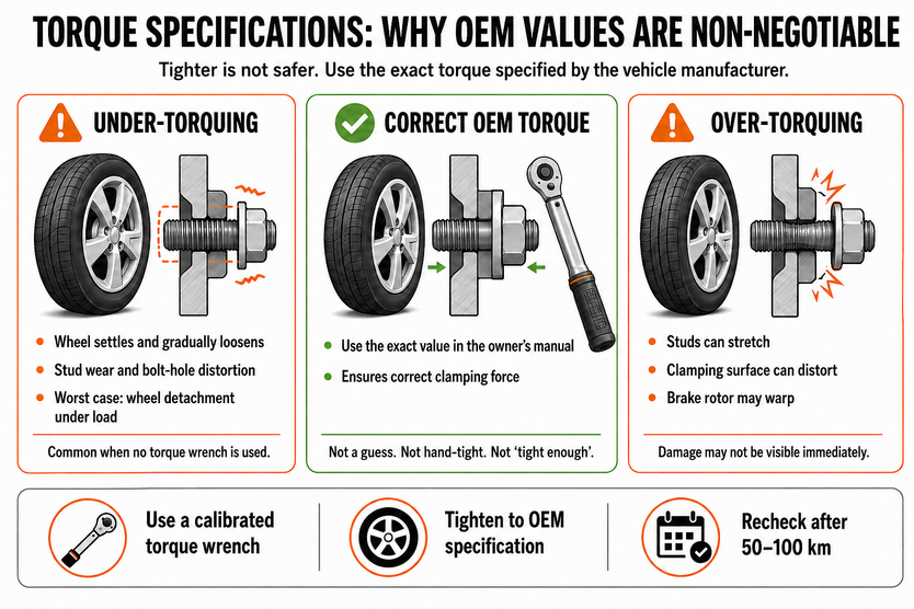
Tighter is not safer. Over-tightened wheel nuts stretch the studs, distort the clamping surface, and in some cases warp the brake rotor. The damage is invisible from the outside and only becomes clear when braking performance drops or a stud fails under load.
OEM torque values are not conservative guidelines. They are calculated stress thresholds, based on the material properties of the stud, the nut, and the hub, set to deliver the exact clamping force needed to hold the wheel securely under all operating conditions without exceeding the structural limits of any component.
Passenger-car wheel fastener torque specifications vary significantly by vehicle. Always follow the vehicle manufacturer's specified value. That is the number to use, not an estimate, not a feel-based approximation.
Under-Torquing: The Risk of a Loose Wheel
A wheel fitted below the specified torque does not fail immediately. It settles.
During the first 50 to 100 kilometers of driving, normal load forces, vibration, and thermal expansion cause the wheel assembly to shift slightly against the hub. That settling process reduces the initial clamping force applied at fitment. On a correctly torqued wheel, the remaining clamping force is still sufficient. On an under-torqued wheel, it isn't.
Progressive loosening follows. Left unchecked, it produces:
- Accelerated wear on the wheel studs from lateral movement at the hub
- Distortion of the bolt holes in the wheel as the clamping force drops
- Wheel detachment under cornering or braking load in a worst-case scenario
Under-torquing is the more common error. It happens when a standard wheel brace is used without a torque wrench, or when impact gun settings are not calibrated to the vehicle's specification.
Over-Torquing: The Hidden Damage You Can't See
Applying too much torque stretches the wheel stud beyond its elastic limit. A stretched stud loses its ability to maintain clamping force under load. It does not return to its original length when the nut is removed, meaning the next fitment starts from a compromised base.
Over-torquing forces uneven pressure across the wheel flange and hub face. The consequences compound quickly:
- Localized stress points form on exposed brake rotors, causing warping
- Warped rotors produce brake pedal pulsation, often misdiagnosed as pad wear
- Stud threads degrade with each subsequent fitment, reducing long-term clamping reliability
Impact guns without torque-limiting settings are the primary cause. A standard impact gun applies two to three times the specified torque in a fraction of a second.
That single error compromises the entire wheel assembly.
The Correct Tightening Sequence and Retorque Protocol
Tighten in two passes, always in a star pattern.
The star pattern ensures the clamping force distributes evenly across the wheel face as each nut pulls the wheel progressively flush against the hub. Tightening in a circular sequence pulls one side flush before the other, creating uneven seating that no amount of final torque corrects.
Pass one: Set the torque wrench to 50% of the specified value and tighten all nuts in the star pattern.
Pass two: Set the torque wrench to the full specified value and repeat the sequence.
The two-pass method allows the wheel to seat progressively and evenly before full clamping force is applied. A single-pass approach at full torque risks locking one side of the wheel against the hub before the opposite side has made full contact.
After the first 50 to 100 kilometers of driving, retorque all nuts to the specified value. Thermal cycling and initial load forces cause minor settling in the assembly. Retorquing restores the designed clamping force before that settling has the chance to progress.
Load Distribution and Wheel Balance
A mass difference of as little as a few grams at the wheel rim generates measurable vibration at motorway speeds. That vibration doesn't stay at the wheel. It travels through the hub, into the suspension, and through the steering column. What starts as an imperceptible imbalance at low speed becomes a handling problem at 100 km/h and a structural stress problem over time.
Every new tire fitment changes the mass distribution of the wheel assembly. Balancing is not a finishing touch. It is a required step in the installation process.
Static vs Dynamic Balance
Static balance addresses the vertical distribution of mass around the wheel. A statically unbalanced wheel has a heavy spot that causes it to bounce or hop as it rotates. This is measurable on a non-spinning balancer and correctable with weights placed at the lightest point on the rim.
Dynamic balance addresses lateral mass distribution across the full width of the wheel. A dynamically unbalanced wheel generates a side-to-side wobble under rotation, which static balancing alone cannot correct. A computerized dynamic balancer spins the assembly and identifies both the weight and exact position of correction needed on the inner and outer rim edges.
Most modern balancing machines measure both simultaneously. A tire fitted without proper dynamic balancing will cause vibration and will contribute to uneven wear over time, regardless of how precisely it was torqued.
The Maxxis Victra Sport 6 is built for exactly this load-transfer precision. Its reinforced casing and tread architecture maintain even contact across the full footprint under lateral load. Wheel imbalance introduces a rotational irregularity that construction alone cannot compensate for.
A proper balance allows a performance tire to perform as designed.
Structural Consequences of Incorrect Mounting
When a tire is removed after several thousand kilometers of incorrect mounting, the damage tells a clear story. The wear pattern across the tread is uneven. One edge is more degraded than the other. The hub contact surface shows scoring. In some cases, the wheel bolts show signs of fretting, which is micro-movement between mating surfaces that occurs when the clamping force was never sufficient to hold the assembly fully static.
None of that damage appeared suddenly. It accumulated from the first rotation.
None of that damage appeared suddenly. It accumulated from the first rotation.
How Mounting Errors Translate Into Wear and Structural Damage
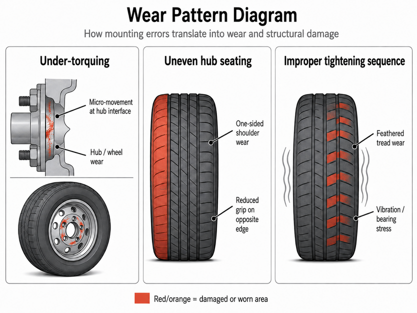
Incorrect torque, uneven hub seating, and improper tightening sequence each introduce a different stress pattern into the wheel assembly. Those stress patterns compound over time and distance.
Mounting Error | Mechanism | Consequence |
|---|---|---|
Under-torquing | Micro-movement at the hub interface creates fretting corrosion | Reduced load transfer area, accelerated wear on hub and wheel |
Uneven hub seating | Tilts the wheel plane relative to the axle centerline, altering camber angle | One-sided shoulder wear, reduced grip on the opposite edge |
Improper tightening sequence | Differential clamping force introduces lateral runout | Vibration, wheel bearing stress, feathered wear across tread blocks |
So if you buy a high-performing tire and expect it to perform as advertised, any of the issues above will cause it to underperform. Tires are designed for consistent tread wear across their full service life in specific weather conditions
The Maxxis Premitra AS AP3, for example, is an all-season tire whose consistency depends on even load distribution from the moment of fitment. The compound and tread architecture can only perform as engineered when the wheel assembly is stable, correctly seated, and uniformly clamped.
EV Platforms: Why Mounting Precision Matters More
An electric vehicle doesn't build power progressively through a gearbox. It delivers full torque to the wheels instantly, from a standstill, every time the accelerator is pressed. That single characteristic changes the mechanical demands on the wheel assembly in ways that a standard passenger car mounting approach doesn't fully account for.
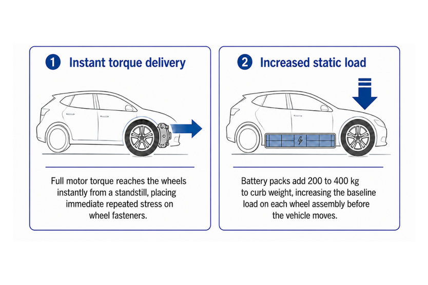
EV platforms impose two compounding demands on the wheel assembly that conventional mounting approaches don't fully address:
- Instant torque delivery — full motor torque reaches the wheels from a standstill, every acceleration cycle, placing immediate and repeated stress on the wheel fasteners.
- Increased static load — battery packs add 200 to 400 kg to curb weight, raising the baseline load on each wheel assembly before the vehicle moves.
Any weakness in the mounting is amplified by both factors simultaneously. An under-torqued wheel on a combustion vehicle may take thousands of kilometers to show progressive loosening. On an EV platform, the same condition is stressed harder from the first drive cycle.
Load Index and Tire Selection on EV Platforms
Standard passenger car tires are rated for loads calculated around combustion vehicle weights. Many EVs exceed those thresholds, which means the load index of the replacement tire is not a secondary consideration. It is a primary one.
Fitting a tire with an insufficient load index on an EV causes the sidewall to operate beyond its designed load capacity. Under sustained stress, the sidewall deforms, heat builds up, and structural degradation accelerates. The consequences compound:
- Sidewall deformation under sustained load
- Heat buildup inside the tire structure
- Accelerated structural degradation over time
Increased blowout risk at combined load and high speed
Always verify the load index against the vehicle manufacturer's specification before fitment. If the EV's documentation specifies a minimum load index, fit at that rating or above.
The Maxxis Victra Sport EV is built around exactly these requirements. Its reinforced construction and compound formulation are developed for the higher load demands and instant torque characteristics of electric platforms. Correct mounting is what allows that engineering to function as intended. A tire designed for EV stress tolerances, fitted incorrectly, carries the same risks as any other tire, compounded by the platform's higher baseline demands.
Post-Fitting Checks: What to Do in the First 100 km
A correctly fitted tire drives cleanly. No vibration through the steering wheel, no pulling to one side, no pulsation under braking. Those sensations, if present after a tire change, are not break-in characteristics. They are installation signals that need immediate attention.
The fitting process isn't complete at the moment the wheel goes on. Two things happen in the first 100 km that require a follow-up check.
First, the wheel assembly settles under real load and thermal cycling. Clamping force reduces slightly as the components find their final position against each other. Second, tire pressure stabilizes as the tire reaches operating temperature. The cold pressure set at fitment may read differently once the tire has been driven on.
Run through the following after the first 50 to 100 km:
- Retorque all wheel nuts to the specified OEM value using a calibrated torque wrench, in the same star pattern used at fitment.
- Check tire pressure cold, before the next drive, and adjust to the vehicle manufacturer's specification.
- Reset the TPMS if the sensor was disturbed during the change, and confirm the system is reading correctly across all four corners.
- Inspect the tire visually for any sidewall bulging, uneven seating against the rim, or debris embedded in the tread.
Monitor steering feel for the first several drives. Pulling, vibration, or steering wheel offset are the clearest indicators of a balance or alignment issue that needs professional assessment.
Correct fitment is also the starting point for getting the most from the car tires on your vehicle. A tire engineered for performance, safety, or efficiency delivers those qualities only when installed according to the standard for which it was designed.